Capacitors for Induction Equipment
Technical Specifications :
| Output | Upto 8‚400 kVAr. |
|---|---|
|
Voltage |
Upto 4‚000 Volts AC |
|
Frequency |
Upto 20‚000 Hz |
|
Tappings |
Tapped / Untapped |
|
Phase |
Single Phase |
|
Cooling |
Water Cooled |
|
Mounting |
Horizontal / Vertical |
|
Casing |
Aluminum / Brass |
|
Case Design |
Isolated (Dead) / Live Case |
|
Protection |
Thermal & Over Pressure Cut–off |
|
Standards |
IEC : 60110–1‚ EN : 60110–1/ 2‚ ISS : 9251 |
Rectiphase was founded by technocrats with three decades of experience in the field of Capacitors and Reactive Power Compensation products. The company´s expertise focuses on design and manufacture of Capacitors for every segment of the power industry‚ e.g. LV‚ MV & HV Power Capacitors‚ PF Correction equipment‚ and for very special applications such as Induction heating & melting‚ Harmonic filters‚ Pulse discharge‚ High energy storage / discharge‚ Surge protection‚ etc. Raw material inputs are sourced from the world´s foremost manufacturers of BOPP film‚ Aluminum foil and insulating oils and manufacturing carried out in an ISO–9001 accredited facility‚ to produce world class capacitor products. All capacitors are extensively endurance and life–tested‚ to comply fully with international & IEC specifications.
Application :
Medium & high frequency water–cooled / air–cooled capacitors are specially designed for use in inductive heating & melting plants for power factor improvement as also for tuning of the circuits for varying inductive loads. These capacitors are manufactured against order to meet the specific and exacting requirements of each customer. For the given application‚ the performance of these capacitors‚ demand extreme levels of Reliability‚ Safety and Life expectancy.
Manufacturing Inputs & Process / Construction :
The capacitor windings (elements) are made from electrical grade double side hazy Bi–axially Oriented Polypropylene film (dielectric)‚ interleaved with soft annealed high purity Aluminum foil (electrode).
These windings and flattened and assembled into a pack for soldering & electrical connections. The entire assembly is subject to very high levels of vacuum‚ under which impregnation is done with a non–PCB electrical grade insulating oil. Water–cooled capacitors are provided with high thermal conductivity copper tubes to facilitate the flow of cooling water. Effective heat dissipation is vital to achieve desired capacitor operating temperature and life expectancy. (Refer to cooling water requirements & recommendations given here below)
Rectiphase water cooled capacitors are uniquely designed to deliver optimum performance at very economic operating cost‚ viz. power loss which are limited to maximum of 0.12 Watts / kVAr on start–up and 0.1 Watts / kVAr after 500 hrs of operation. The extremely low watt losses contribute significantly in enhancing the capacitor life expectancy levels. The dielectric we use is low–loss electrical grade double side hazy bi–axially oriented polypropylene film‚ the structured surface of which ensures 100% impregnation throughout the length of the winding. (See photo alongside)
Watt Loss & Capacitance Variation Graphs : (Dielectric Characteristics)
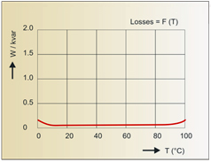
Variation in losses (W/kvar) as a function of temperature
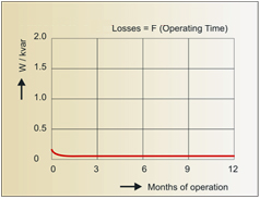
Variation in losses (W/kvar) as a function of operating time
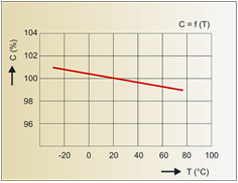
Variation of capacitance C(μF) as a function of temperature
Connections :
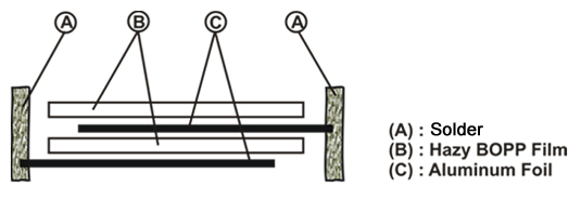
Figure 1 : Sectional view of winding & connections.
The electrode connections are done by a special process of soldering the extended portion of the aluminum foil of each element‚ guaranteeing excellent electro–mechanical contact and low tan–delta (Tan δ)‚ resulting in low operating temperature and enhanced operating life (Refer Figure 1). The un–divided (single)/ sub–divided (multiple) sections are connected accordingly to provide for the required single / multiple Section CN / kVAr out–puts.
Insulating Fluid :
The insulating oils we use have very high thermal stability‚ high flash point (146°C)‚ high fire point (154°C)‚ good hydrogen gas absorbing capacity and excellent heat transfer co–efficient characteristics‚ thereby ensuring lower operating capacitor temperature and enhanced operating life. These are non–PCB‚ non–toxic‚ and bio–degradable.
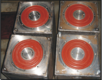
Casing :
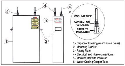
General arrangement of Water–Cooled Capacitor.
Water–cooled capacitors are supplied with aluminum sheet casing‚ either painted or having original aluminum / stucco embossed finish. On specific request we supply brass sheet casing (painted). For line / low frequency applications Non–magnetic SS casing.
Insulators & Connection Hardware :
The insulators are made from high temperature molded bakelite having excellent electro–mechanical properties. Connection hardware is of Brass (non–magnetic)
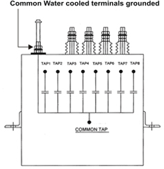
Capacitor Configurations :
Capacitors can be supplied with either of the following configurations depending on the applications & customers requirements.
Configuration 1 : Single cooled–live case design‚ with sub–sections. (one terminal connected to casing)
Configuration 2 : Single cooled–isolated / dead case design‚ with sub–sections. (all terminals isolated)
Configuration 3 : Double cooled–isolated / dead case design‚ without sub–sections. (all terminals isolated)
Configuration 1
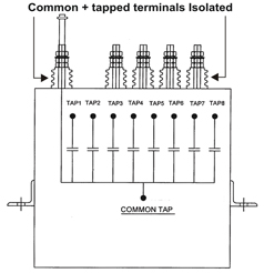
Configuration 2
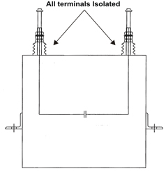
Configuration 3
Cooling Water Requirements :
The performance and operating life of water–cooled capacitors are determined by effective cooling conditions. As water–cooling plays a vital role‚ all related parameters such as water quality‚ required minimum & maximum water flow‚ water pressure‚ in–let and out–let water temperature‚ assume critical importance and must be closely monitored to achieve desired results. (Refer relevant charts & recommendations).
- Rated water flow should be minimum 5 L/min. Maximum pressure drop of 140 m bars.
- In–let water temperature should not exceed 35°C & out–let water temperature should be limited to maximum 45–50°C. Ideally‚ the difference between the in–let & out–let water temperature should be around 10°C.
- Pressure drop for ½” OD cooling tube & required water flow in L/min.
| Drop (PSI) | Flow Rate (L/min) |
|---|---|
|
0.3–0.4 |
3.8 |
|
0.9–1.1 |
5.7 |
|
1.6–2.1 |
7.6 |
|
2.5–3.4 |
9.5 |
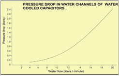
Pressure Drop in Water Channels of Water Cooled Capacitors
We strongly recommend the use of demineralized water as the cooling medium which should be chemically neutral & mechanically pure. The maximum contamination limits of the cooling water are as under.
| With carbonate hardness | 8°DH | 6°DH | 4°DH |
|---|---|---|---|
|
PH Value |
7.8 |
8.1 |
8.3 |
|
Free (Co2) |
8mg/l |
4mg/l |
3mg/l |
|
Aggressive (Co2) |
not allowed |
|
|
|
Ammonia (NH3) |
not allowed |
|
|
|
Nitrides (NO2) |
0.04mg/l |
|
|
|
Iron |
0.03mg/l |
|
|
|
Manganese |
0.05mg/l |
|
|
|
Sulfates |
250 mg/l |
|
|
|
Chlorides |
150 mg/l |
|
|
|
KMnO4 consumption |
15 mg/l |
|
|
Protection :
- Fuses :
Fuses are not provided for medium / high frequency capacitors for Induction equipment. However line frequency capacitors of 50/60 Hz are provided with internal element fuses.
- Thermal (Optional) :
We offer thermal cut–off protection, which detect excessive capacitor temperature / case over–heating and trip the system in case of heating beyond preset limits‚ to prevent capacitor failure.
Over Pressure (Optional) :
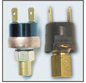
Over–pressure protection is rendered through externally mounted pressure switches to detect excessive pressure formation within the container and ensure rapid disconnection of the capacitor to prevent violent failure‚ or case rupture. (see photo alongside)
Residual Voltage :
Capacitors for induction equipment applications are normally connected across the induction coil‚ which ensures rapid discharge of the residual voltage on disconnection from the supply. Therefore a separate discharge device is not provided unless specifically requested. Provision of such a discharge device protection is essential if the capacitors are switched off and re–energized at very short intervals or if the installation has an isolating switch / device connected between the capacitors and the induction coil / any other discharge paths.
Mounting & Installation :
Capacitors can be positioned vertically (terminal up–wards) or horizontally (terminal side–wards) and are suitable for open rack mounting or inside the furnace inverter panel. The capacitors must be installed indoors. Mounting / Fixing brackets can be provided to meet customers convenience / requirements.
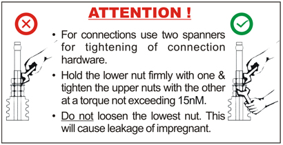
Precautions & Handling Instructions :
Do not lift or handle capacitors by the bushing terminals / ends of the cooling–coil tubes. Before handling a capacitor unit / capacitor bank ensure that the unit is completely isolated from the supply and properly discharged‚ by repeatedly short–circuiting all its terminals with a thick insulated wire bared at both ends.
The use of non–magnetic fixing and connection hardware is strongly recommended. Magnetic material should not be located close to‚ or be in contact with the units‚ while in operation.
Ensure water flow through the capacitor cooling–coil before energizing in normal operation. Cooling water circulation hoses for interconnection with external cooling pipes or between individual units should be flexible‚ non–conductive‚ and of carbon–free‚ synthetic rubber or polymer material. The cooling–coils of capacitors left idling or in freezing conditions must be blown free of all contaminants / blockages with compressed air before energizing.
Tightening of terminals play a vital role in the satisfactory functioning of these capacitors. Tightening of terminal connection nuts to more than 15 nM is not recommended. Excessive torque may damage gaskets or strip terminal threads. Use two spanners for tightening terminal connection nuts as shown in the illustration alongside.
Tests :
Every unit undergoes the following tests before dispatch :.
- Capacitance measurement.
- Voltage test between terminals‚ 2 x UN AC for 10 seconds‚ or 4 x UN DC for 10 seconds.
- Voltage test between terminals and casing‚ 2.15 x UN AC for 10 seconds‚ minimum voltage 2kV. (Applicable for isolated case design only)
- Loss factor measurement at 50 Hz.
- Leakage test for capacitor casing‚ pressure / thermal protection switches (if provided).
- Leakage test from cooling coil.
Technical Data :
| Dielectric | Electrical Grade Hazy BOPP Film |
|---|---|
|
Electrode |
Aluminum Foil |
|
Insulating Fluid |
Non–PCB‚ Biodegradable‚ Non Toxic |
|
Out–Put |
Up to 8400 kVAr |
|
Rated Voltage |
Up to 4000 Volts AC |
|
Rated Current |
Not Exceeding 4000 Amps |
|
Rated Frequency |
50 Hz–20‚000 Hz |
|
Terminals |
Un–Tapped (Double cooled) : All terminals Water–cooled.
Tapped (Single cooled) : 2 Water–cooled terminals + taps |
|
Temperature Category |
Up to 50°C |
|
Overload Limits |
Voltage : 1.05 X UN for maximum 12 hours /day Current : 1.15 X IN |
|
Terminal Insulators |
Electrical grade molded bakelite |
|
Terminations |
Extruded Brass‚ with non–magnetic connection hardware |
|
Protection |
Thermal & Over–pressure Cut–off (Optional) Residual Voltage : Discharge device is provided only on request |
|
Unit Mounting |
Horizontal–Terminals side wards / Vertical–Terminals up wards |
|
Cooling Medium |
De–mineralized water |
|
Required Water Flow |
Minimum 5 L/min |
|
Cooling Tubes |
½” Electrolytic grade copper tube |
|
Ref Standards |
IEC : 60110–1/2‚ EN:60110‚ ISS: 9251‚ VDE–0560 (Part–9) |
Information Required With Inquiry / Order :
The following data should be furnished with an inquiry or an order :
| Rated output | kVAr |
|---|---|
|
Capacitance |
CN (μF) |
|
Tolerance on Capacitance |
– ____% / + ____% |
|
No. of Sub–divided Sections |
|
|
Details of equal / un–equal Sub–divided Sections |
|
|
Rated voltage |
Volts AC |
|
Rated frequency |
Hz / kHz |
|
Cooling |
Air / Water. (Single / Double cooled) |
|
Casing Design |
Dead case (Isolated) / Live case
(one terminal connected to the casing) |
|
Case material |
Brass / Aluminum |
|
Internal fuses |
|
|
Discharge Device |
|
|
Protection |
Pressure / Thermal switch |
|
Standards |
|
|
Mounting |
Vertical / Horizontal |
|
Preferred Dimensions |
|
|
Special requirements |
|
Formula :
| Rated voltage | UN……………KV |
|---|---|
|
Rated frequency |
FN……………kHz |
|
Rated capacitance |
CN……………μF |
|
Rated output |
QN……………kVAr |
|
Rated current |
IN……………Amps |
- Formula for Output :
QN = UN2 x CN X 2π X FN [kVAr; kV; μF; kHz].
- Formula for IN [Amps] :
IN= QN / UN [A; kVAr; kV].
- Example :
UN = 1.5 kV. CN = 424.36 μF. FN = 0.5 kHz.
QN = 1.52 x 424.36 X 2π X 0.5 = 3000 kVAr
IN = 3000 / 1.5 = 2000 Amps
Quality System & CE Marking :
Quality Assurance System ISO–9001 is adhered to. Capacitors for Inductive heating & melting plants cannot be provided with CE marking as these are not included in the scope of the European Community guidelines as per the European Union (EU) manual.
Emergency Replacements :
We supply Capacitors required as replacements in induction furnaces‚ with every effort to closely match dimensions of the failed units. Please contact us with a sketch of the failed capacitor‚ showing critical parameters such as terminal arrangements and case dimensions. Shipments against such emergency orders are made in less than 2 weeks. Like all our products these capacitors are supplied with a 24 month guarantee.
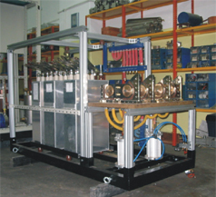
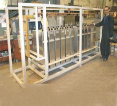
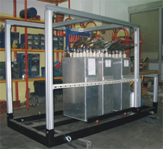
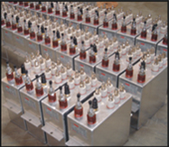
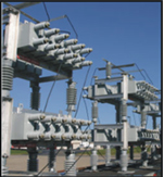
Capacitors Under Assembly At Our Overseas Customers Plants
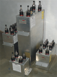
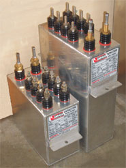
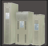
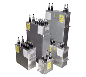
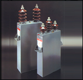
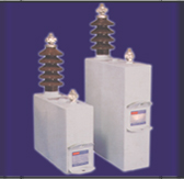
Range Of Water Cooled Capacitors
Our Range Of Capacitor Products :
Capacitors for Induction Equipment
Energy Storage Capacitors
Harmonic Filters
HV Power Capacitors
Surge Capacitors