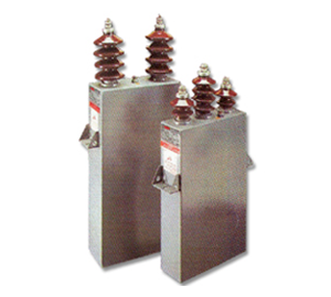
Medium and High Voltage Capacitors
When it comes to Medium & High Voltage Power Capacitors‚
and Reactive Power Compensation!
ECOVAR is the name you can trust.
ECOVAR is a product backed by 30 years of rich and dedicated experience of technocrats who have worked on and excelled in application engineering‚ design‚ manufacture and installation of Power Capacitors & Reactive Power Compensation equipment for transmission networks up to 145 kV. This brochure elaborates the details of our manufacturing technology‚ material inputs‚ fusing techniques‚ economics of installation & operation‚ configuration options‚ with relevant protection schemes and switching / protection accessories that are within our current engineering capabilities.
General :
ECOVAR High Voltage Power Capacitors are manufactured at our Sinnar Plant in India‚ which is an ISO–9001 accredited facility & houses a computer aided design‚ manufacturing‚ processing and testing infrastructure that ensures all products manufactured strictly comply with domestic and international standards‚ and perform to the highest levels of safety‚ reliability and life expectancy.
Technology and Basic Construction :
Amongst most electrical products‚ Power Capacitors are highly susceptible to premature failures if improperly installed or if the application or load profiles are non–linear or the system parameters are erratic. It is therefore of atmost importance that capacitors are designed to perform under such onerous conditions. Hence material selection‚ quality inputs‚ design‚ manufacturing and processing parameters assume critical importance.
ECOVAR High Voltage Power Capacitors are manufactured from raw material inputs sourced from the world´s foremost manufacturers of plastic film dielectrics‚ aluminum electrode foils‚ and electrical insulating fluids.
ECOVAR Capacitors generally utilize the following raw materials unless special end use applications necessitate use of alternative material :
- Dielectric : Electrical Grade Double–Side–Hazy Biaxially Oriented Polypropylene Film.
- Electrode : High Purity Soft Annealed Aluminum Foil.
- Impregnant : Phenly Xylyl Ethane (PXE) / Jarylec‚ Non–PCB‚ Non Toxic‚ Biodegradable.
- Housing : Stainless Steel / Mild Steel Sheet.
- Bushings : Soldered or Welded‚ Brown / Gray‚ Glazed Porcelain Insulators.
- Exterior finish : Etched Primer with Final Coats of Epoxy Paint.
Power Loss :
ECOVAR Power Capacitors are uniquely designed to deliver optimun performance at very economic operating cost‚ viz. power loss which are limited to maximum of 0.12 Watts / kVAr on start–up and 0.1 Watts / kVAr after 500 hrs of operation. The extremely low watt losses contribute significantly in enhancing the capacitor life expectancy levels.
Watt Loss & Capacitance Variation Graphs :
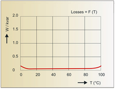
Variation in losses (W/kvar) as a function of temperature
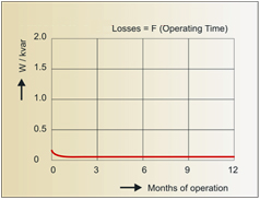
Variation in losses (W/kvar) as a function of operating time
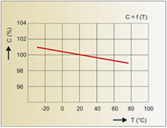
Variation of capacitance C(μF) as a function of temperature
Fusing Techniques :
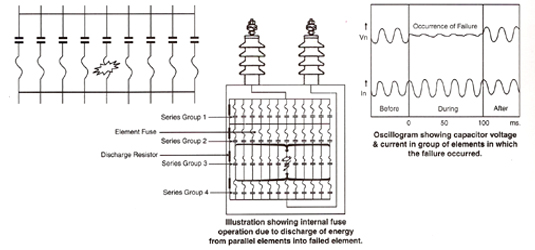
- Internal Fuse Design :
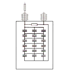
ECOVAR Capacitor units are generally provided with internal fuses across each element for rendering internal protection to the capacitor unit in case of a fault occuring within the element winding. These fuses are designed on the basis of stored energy principle and coordinated to withstand all normal and some abnormal system overloads and disturbances and to render overall unit protection. (Refer to detailed internal fuse technical write–up available on request). ECOVAR Capacitor units are also offered with option of conventional external fuses (Expulsion type / HRC type) depending on the unit kVAr rating as also application and severity of protection required.
Externally Fused Cell
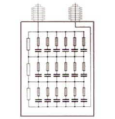
Internally Fused Cell
- Diagram Showing Internal Fusing Of Element In One Series Group :
- External Fuse Design :
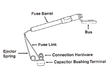
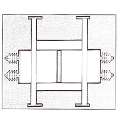
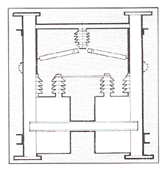
An expulsion fusing system as used for protecting capacitors consists of three components which include the fuse tube / barrel‚ the fuse link‚ and the ejector spring. The proper operation of a fuse is dependent upon these components working in close harmony with each other. The illustrations below show the fuse assembly operation & visual indications of the fuse in fused and blown fuse position.
Proper assembly of the fusing system is critical to the successful operation of the fusing system whereas incorrect installation may result in severe damage to the fuses‚ the capacitors‚ and / or capacitor bank.
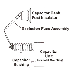
Expulsion fuse mounting arrangement
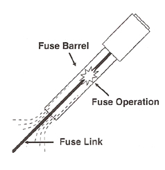
Fuse link operation inside barrel
Spring in Fused Position
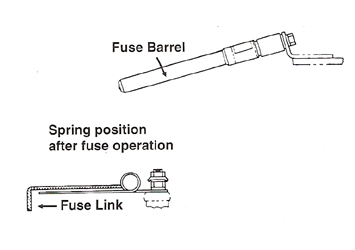
Spring in Blown Fuse (Indicating) Position
Technical Comparison Between Internally & Externally Fused Capacitor Banks :
| Parameter Of Comparison | External Fusing | Internal Fusing |
|---|---|---|
|
Fuse isolates only the failed / faulty element |
No |
Yes |
|
Capacitor unit is isolated on fuse operation |
Yes |
No |
|
Reduction in Bank output after fuse operation |
Considerable |
Negligible |
|
Reduction in unit life after fuse operation |
Unpredictable |
Marginal |
|
Bank with cells of higher kVAr Out–put |
No |
Yes |
|
Reliability of fuse co–ordination / unbalance protection |
Un Predictable |
Vary Reliable |
|
Case rupture protection |
Yes |
No |
|
Economy in cost of installation |
No |
Yes |
|
Space requirement for installation |
Occupy More Space |
Occupy Less Space |
|
Visual indication of fuse operation |
Yes |
No |
|
Terminal to case insulation protection |
Yes |
No |
|
Consistency in fuse operation / protection |
No |
Yes |
|
Fuse is subject to routine electrical testing along with the unit |
No |
Yes |
|
Fuse is protected from environmental hazards |
No |
Yes |
|
Cost of structural steel & weight |
Higher |
Lower |
|
Convenience of assembly and connections |
Cumbersome |
Convenient |
|
External electrical clearances |
Are Less |
Are More |
|
Unit replacement in case of failure |
Convenient |
Cumbersome |
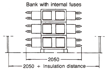
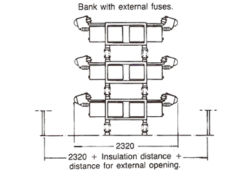
Illustration showing Space saving & External Clearances
Types Of Mounting :
Capacitor banks can be offered with option of units mounted horizontally or vertically‚ performance parameters remaining the same in either case. However for space saving‚ compactness‚ and better clearances in case of moderately sized or larger rated outdoor installations‚ horizontal mounting is recommended. Internal or external fusing can be offered for both types of mounting options.
Internally Fused Horizontally Mounted Units
Externally Fused Vertically Mounted Units
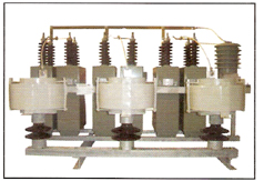
Pole Mounted Capacitors :
Pole Mounted Capacitor Banks can be offered with power out–puts from 300 kVAr to 1200 kVAr. These are operated with automatic vacuum / gas insulated switches‚ and find applications on rural feeders‚ where monitoring is difficult hence warrant a virtually maintenance–free installation. These capacitors are usually offered with external fuses‚ as bank and unit ratings are small. However‚ dual fusing techniques are also offered‚ as this helps not only in preventing case rupture due to dual protection‚ but also ensure that the external fuses do not operate fictitiously as the internal fuses take care of most of the faults‚ leaving the external fuse to operate only in case of a container to pack insulation failure / major external fault.
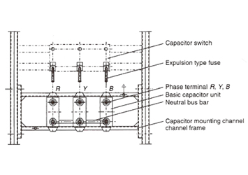
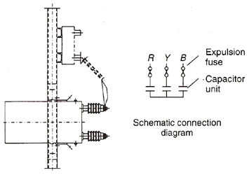
Typical arrangement of externally fused pole mounted capacitor bank
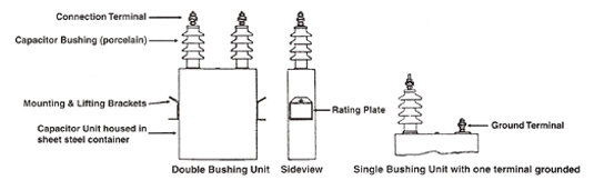
General Arrangement Of ECOVAR Capacitor Unit :
Bank Connections & Configurations :
Capacitors Banks can be offered with option of the following configurations :
- 3 Ø Delta Connected.
- 3 Ø ‘Y’ Connected.
- 3 Ø ‘Y–Y’ Connected.
- 1 Ø ‘H’ Connected (Traction Duty Application for Railways).
For ‘Y’ / ‘Y–Y’ connected capacitor banks the star point is usually kept floating & used for sensing voltage & current unbalance. Accordingly‚ suitable unbalance protection relays are provided on the control & relay panel to provide for tripping the bank on occurrence of severe unhealthy or unbalanced conditions. Below are connection diagrams that indicate various configurations & protection techniques. Also‚ detailed herein are various protection schemes with switching & protective accessories.
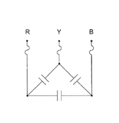
Delta Connected Capacitor Bank
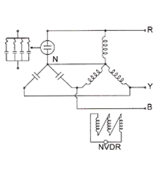
‘Y’ Connected Capacitor Bank With Voltage Unbalance Protection
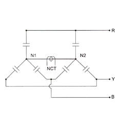
‘Y – Y’ Connected Capacitor Bank With Current Unbalance Protection
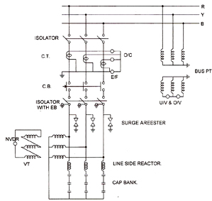
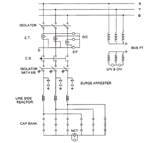
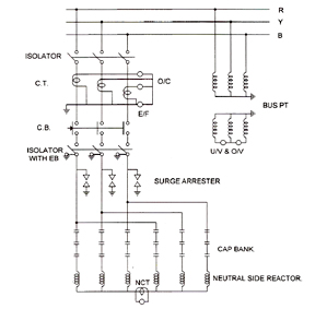
Capacitor Bank Control & Protection Schemes :
Universally practiced switching and protection schemes are designed and engineered to render total and thorough protection to the capacitor installation from internal abnormalities as also from external system disturbances or hazards. It is strongly recommended to provide over–voltage‚ under–voltage‚ over–current‚ earth–fault‚ ‘ON’ time delay and unbalance protection to capacitor bank installations. Some typical protection schemes are shown in the schematic diagram below.
‘Y’ Connected Capacitor Bank With Switching & Protection Equipment :
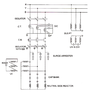
‘Y – Y’ Connected Capacitor Bank With Switching & Protection Equipment :
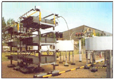
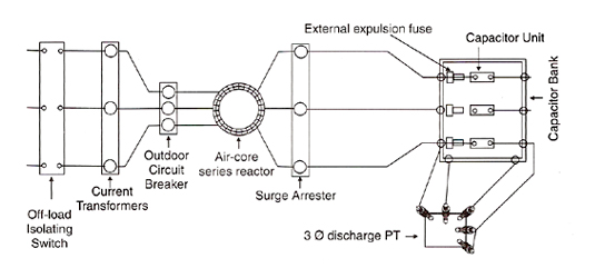
Typical Layout Of An Outdoor Capacitor Installation :
Shown alongside is a typical layout of outdoor capacitor installation along with relevant switchgear and protection equipment.
Reference standards :
ECOVAR High Voltage Power Capacitors can be offered to comply with various international standards‚ such as :
| IS : 13925 & IS : 12672 | IEC : 60871 | NEMA : CP–1 | CEI : 33–7 | VDE : 0560/4 |
|---|---|---|---|---|
|
BS : 1650 |
ANSI : IEEE Std–18 |
French : C–54102 |
CSA : C.22–2 No 190 |
AS : 2897 |
Range :
| Unit Voltage : 1.1 kV to 24 kV | Bank Voltage : 3.3 kV to 145 kV |
|---|---|
|
Unit Out–put : 50 kVAr to 600 kVAr |
Bank Out–put : 300 kVAr to 50 MVAr |
Basic Insulation Levels :
The insulation levels for capacitor banks for various voltage networks are given in the table below :
| Basic Insulation Level of bank | kV (SYSTEM) | 12 | 24 | 36 | 72.5 | 123 | 145 |
|---|---|---|---|---|---|---|---|
|
Power Frequency withstand Voltage |
kV (RMS) |
28 |
50 |
70 |
140 |
185 |
230 |
|
1.2/50 ms impulse withstand Voltage |
kV (PEAK) |
75 |
125 |
170 |
325 |
450 |
500 |
Permissible Over Loads :
Capacitor cells and banks may be required to perform under stressed and overloaded conditions for certain durations. The permissible upper limits with respect to voltage and current overloading and the corresponding durations are :
Current :
1.30 times rated current continuously.
Voltage :
1.10 times VN for 12 hrs in a duration of 24 hrs.
1.15 times VN for 5 min. in a duration of 24 hrs.
1.30 times VN for 1 min. in a duration of 24 hrs.
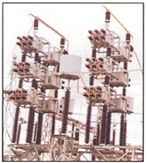
HV Capacitor Bank & Harmonic Filter Installations With Reactors :